MSS SP-75 specification applies to factory-made seamless and electric welded carbon and low alloy steel, butt welded pipe fittings for high pressure oil and gas delivery and distribution systems, including pipelines, compressor stations, metering and regulating stations, and main pipelines.
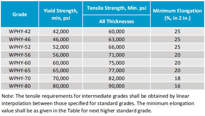
MSS SP-75 fittings material includes Grade WPHY-42, WPHY-46, WPHY-52, WPHY-56, WPHY-60, WPHY-65, WPHY-70, and WPHY-80. Which corresponding to the API 5L Pipe standard X42 to X80.
MSS SP75 WPHY 60, WPHY 65, WPHY 70: Common Use Grades
MSS SP-75 Grade WPHY 60, 65, and 70 are used a lot in the high pressure oil and gas pipeline fittings, for WPHY-42, 46, 52 and 56, they are working in a medium-high pressure pipelines, so mostly client may choose with ASTM A234 WPB or WPC instead.
MSS SP75 WHPY 60, yield strength 60,000 psi, tensle strength 75,000 psi.
MSS SP75 WPHY 65, YS 65,000 psi, TS 77,000 psi.
MSS SP75 WPHY 70, YS 70,000 psi, TS 82,000 psi.
The standard specifies the dimensions, tolerances, ratings, materials, chemical composition and tensile properties, heat treatment, notch toughness, manufacturing and marking of quality butt welded pipe fittings for NPS 60 and smaller. Normally for NPS14 and smaller butt weld pipe fittings referred to ASME B16.9.
Pressure Ratings
The allowable internal pressure ratings for straight seamless steel pipe (or welded steel pipe with a joint coefficient of 1.0) of equivalent grades and diameters and wall thicknesses shall be calculated in accordance with the rules established in the applicable section of ASME B31 and in accordance with the fittings designed in this standard specification.
According to MSS SP-75, all fittings made shall be designed to support the field hydrostatic pressure test at a pressure level . This pressure level is equivalent to the pressure level required to form an hoop stress. Based on the Barlow formula, the hoop stress is equal to the specified minimum yield strength for pipe of equivalent grade and wall thickness under the condition of no damage, leakage or failure.
Barlow's formula
It is defined as:
P = 2St/ D
Where:
P= internal design pressure, psig;
S= specified minimum yield strength of the pipe, psi;
t= nominal wall thickness of the pipe, inches;
D= outside diameter of the pipe, inches.
Size
The nominal size of the pipe fitting is shown in the nominal outside diameter of the pipe to which it is connected.
Design Proof Test
When the manufacturer selects a proof test to ensure the quality of the fitting design, the test shall be performed in accordance with the provisions of this standard practice. It shall be based on the calculated burst pressure of the fitting and its connecting piping as defined in Section 4.3. Factory-made segmented elbows need proof test on geometrically similar 90-degree elbows without the need for separate testing.
Test Assembly Requirements
Fittings with the same basic design configuration and manufacturing method shall be selected for testing from production. And it shall be determined for materials, grades and batches, including heat treatment. They should be checked for compliance with the dimensional requirements of this standard.
Straight Seamless or Welded Pipe
The calculated bursting strength of a straight seamless or welded pipe is at least as great as the proof test pressure calculated in Section 4.3. And it shall be welded to each end of the fitting to be tested. The nominal wall of the pipe section may be larger than the thickness indicated by the assembly marking. The greater thickness shall not exceed 1.5 times the nominal pipe wall thickness as identified by the fitting markings. Any internal misalignment greater than 0.06 inches shall be reduced by taper boring at a slope, not more than 1:3 (18°). For greater than NPS 14, the minimum length of pipe sections for closures shall be one-half pipe, and it shall be one pipe fpr NPS 14 and smaller.
Test Fluid
The test fluid should be water or other liquid. Hydrostatic pressure should be applied to the assembly. It is recommended to perform at least three proof tests for each fittings, join size or configuration. Meanwhile it shall be taken to rupture or held at or above computed minimum proof pressure for a period of at least 3 minutes. For more details contact us for MSS-SP75 pdf details.
Materials
The steel should be fully "killed" and manufactured using accepted smelting methods to provide intended heat treatment response and notch toughness. Steel shall be suitable for on-site welding of other fittings, flanges and pipes manufactured in accordance with the applicable specifications listed in the ASME B31 specification.
The pipe material shall be steel ingots, billets, sheet steel, forged quality bars, steel plates, seamless welded or welded pipes with additional filler metal.
The steel used shall be of suitable welding quality carbon steel or high strength, low alloy steel of suitable welding quality.
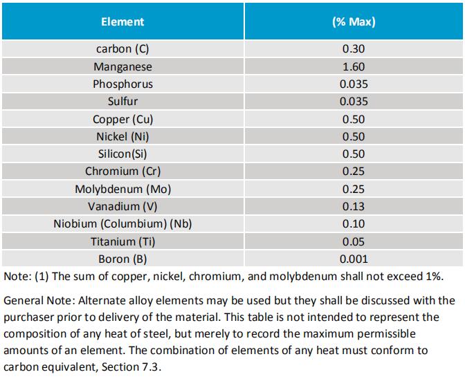
Chemical Composition of MSS-SP75 Fittings

Mechanical Strength for WPHY 42, 52, 60, 65, 70

Heat Treatment
All fittings should be delivered under heat treatment. Hot formed fittings should be cooled below the critical temperature prior to heat treatment. The pipe fittings shall be subjected to one or more heat treatments as specified below.
Stress Relief
Unless otherwise requested by the purchaser and the manufacture, stress relief should be limied to guide bar welds. Fittings should be heated to a suitable temperature below the transition range, but not below 1000 °F. The holding time should be no less than 1 hour/in and the minimum should not be less than 0.5 hours, and then placed in the furnace or cool in air.
Normalizing
The pipe fittings should be reheated evenly above the transition temperature (austenite zone), at which temperature the hold time should be long enough to reach uniform temperature, and then cooled in air.
Normalizing and tempering
The pipe fittings shall be normalized in accordance with the normalizing regulations. Then reheat to a suitable temperature below the transition temperature, but not below 1000°F for tempering. The holding time should not be less than 1 hour / in, and the minimum should not be less than 0.5 hours, and then placed in the furnace or cool in the air.
Quenching and tempering
The fitting should be uniformly reheated above the transition range, maintained at a temperature sufficiently to achieve a uniform temperature throughout the material, and immediately immersed in a suitable liquid medium. Then reheat and temper according to the rules of normalizing and tempering. The quenching facility should be of sufficient size to ensure that the pipe is evenly cooled.
Manufacturing Procedures Specification (MPS)
Fittings shall be manufactured in accordance with documented MPS. If the purchaser specifies, manufacturing must not be carried out until the purchaser accepts the MPS.
It should indicate the following items, if applicable:
a.For starting materials:
1). Product form (seamless or welded) and size,
2). Welding NDE results if the fittings manufacturer does not complete.
b.For fitting manufacture
1). Forming method
2). Welding procedure specification and approval record, if applicable
3). Heat treatment procedure including thermal cycles
4). Machining requirements
5). Inspection, dimensions and test requirements
6). Proof test results if requested
7). Traceability
c.Additional requirements such as end preparation, coating and marking.
The fittings can be fabricated by forging, hammering, pressing, drawing, stamping, extruding, welding, or some combination of these operations. The molding steps used should not cause harmful defects in the pipe fittings.
Tees, elbows and other fittings are made using circumferential or intersection welds (eg, miter welds). They are considered to be pipe manufacturing, and are outside the scope of this standard practice.
All outlets for NPS 2 and larger shall be of integral profile, and the outlet end shall be matched to the specified connection pipe or fitting.
Welding Manufacturing
Machine Welding
Machine welding should be carried out using an electrical process, and submerged arc welding is better.
Butt Weld
All butt welds should be completely penetrated. Submerged arc welders should be welded at least once from the inside unless the accessibility makes it impossible. Then, if the root weld can be visually inspected, a manual or machine root weld bead can be adopted. Do not use the backing ring.
Repair, Chipped and Ground
The weld shall be repaired, chipped or ground in a manner that does not create gouge, grooves, or reduce the thickness of the raw material not exceeding 6.5% of the specified nominal wall thickness.
Fillet Weld
Fillet welds shall have full weld throats a. If not otherwise specified, the two weld legs shall be approximately equal length.
If a welded bracket is used, it should be removed prior to heat treatment and the weld spot need to be repaired and ground flush, and smoothed. However, if brackets are required for heat treatment, they should be cut off ,and the surface should be ground flush nd smoothed after heat treatment. Welding is not allowed after heat treatment.
Workmanship and Finish
Pipe fittings should not have harmful defects, and the surface should be smooth and flat. However, when depth exceeds 6.5% of the nominal wall thickness, the defect is defined as a injurious defect.
Surface defect treatment
If harmful defect, such as notches, scratches, scabs, seams, laps, tears, or slivers, not deeper than 6.5 %, and it should be removed by grinding method. The defect can be repaired by welding process. When the depth of the defect exceeds 33.3% of the nominal wall thickness or the repair length exceeds 25% of the specified diameter, the harmful defect can’t be repaired. However, it must be completely removed and welded by a qualified welder.
Our Supply Range for MSS SP-75 WPHY Fittings
Standard: MSS SP-75
Grade: WPHY 42, WPHY 46, WPHY 52, WPHY 56, WPHY 60, WPHY 65, WPHY 70, WPHY 80
Types: Butt Weld Fittings
Size Range: 1/2”, 1”, 2”, 3”, 4”, 6”, 8”, 10”, 12”, 16”, 20” to 60”.
Thickness: SCH 10, SCH 40, SCH 80
Surface Coatings: Black Painted, Varnished, Epoxy Coated, Galvanized


